Robotics Tool-pathing and Programming
Automation for large-scale 3D printing
The large-scale 3D-printing process can be broken down into three main parts. First, you begin with a robot arm and a digital model of what you want to print. Next, you perform operations on that model in order to generate toolpaths and actions for a robot to perform. The output of this step is a block of program code that the robot uses to perform the print. The third step is physically printing the object on the robot with said program.
The bulk of time and effort is spent in the second step, which involves heavy use of automation and optimization in order to streamline the process.
First Phase: Digital Model and robot limitations
The first step is to understand the limits of the printing system, and whether or not the object is printable. This phase involves understanding the robot and it’s print limits. this will allow for diagramming and drawing out print strategies to make sure the object fits within the printing limits of the system.
Second Phase: Toolpathing
The second phase involves taking the digital model and creating a print logic from the geometry. The software required to compile code in the robot’s native language is a bit complicated; a diagram of a typical workflow is shown below.
The process from model to print paths usually involves slicing the form based on a layer height, and taking the resulting lines and creating coordinates for the robot to move to. Once these coordinates and the print logic is generated, a robot program is written.
Third Phase: Testing and Printing
Once the program is uploaded to the robot, the printing and testing can begin. This process is a back-and-forth between printing an object, analyzing the printed object, and updating the code based on lessons learned. Over time, a base of knowledge is built up and reflected in the program script in order to streamline future prints.
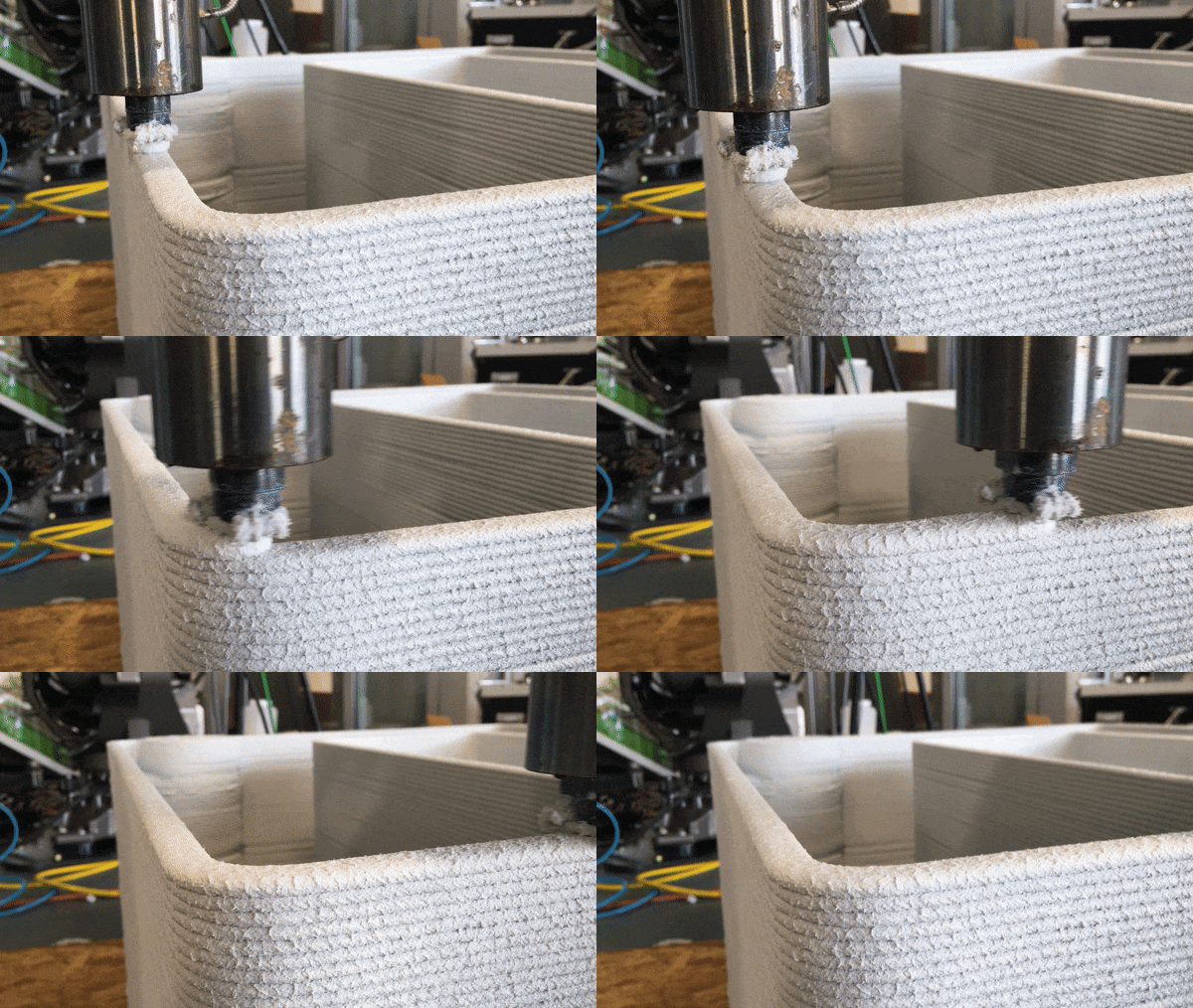
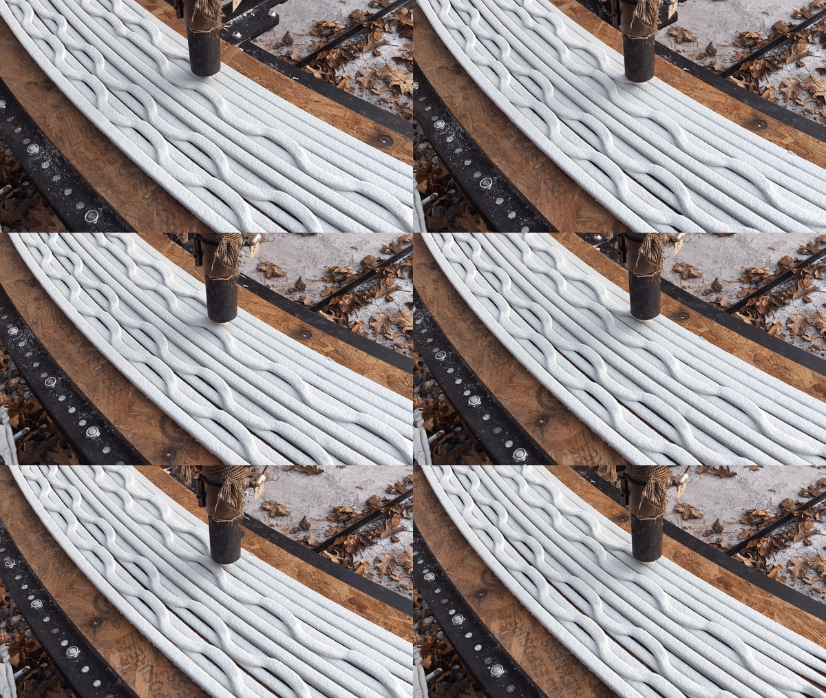
The video above shows a series of tests that led to the printing of a large-scale cylinder. Along the way, there were many lessons learned, such as the material’s self-leveling tendencies, tool-path optimizations, and other various tests to further understand the material we were printing with.
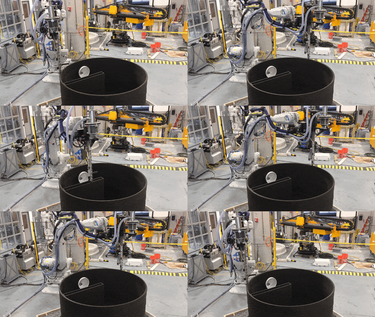
The lessons learned from testing and printing were used in the logic for a large-scale print, shown here. The cylinder was printed on a bed of gravel, and the self-leveling strategy allowed us to print a flat slab as support for the cylinder above.


